CNC Machining Metal Parts +86-18169936698
Blog
We offer metal fabrication service and custom manufactured parts factory service

The Revolution in CNC Machining of Large Parts: Solving the Vibration and Deformation in Heavy Workpiece Processing
In modern manufacturing, the machining accuracy of large structural components—such as wind turbine nacelles, aerospace frames, ship engine housings, and heavy machinery machine beds—directly determines the performance and lifespan of the final product. As industrial equipment trends toward larger sizes, lighter weight, and higher load-bearing capacities, these heavy workpieces often measure several meters or even tens of meters in size and weigh from several tons to over a hundred tons.
However, when these “giants” are mounted on the worktable of a CNC machine tool, a tricky physical problem immediately emerges: vibration and deformation. These two “invisible killers” not only lead to increased tool wear and deteriorated surface finish but, more critically, cause dimensional deviations, potentially scrapping workpieces worth hundreds of thousands of dollars. This article will delve into the causes of vibration and deformation in large-part CNC machining and reveal how modern manufacturing technology successfully resolves this worldwide challenge through process innovation and equipment upgrades.
Chapter 1: “Pathology Analysis” of Vibration and Deformation
Before discussing solutions, we must understand the nature of the problem. Vibration and deformation in large-part machining are not caused by a single factor but are the result of the interplay between physical mechanics, material properties, and cutting parameters.
1. Rigidity Imbalance: Workpiece Rigidity vs. Tool Rigidity
In conventional machining, we typically assume the workpiece is much more rigid than the tool. However, in large-part machining, the opposite is often true.
-
Thin Walls and Hollow Structures: To reduce weight, large parts (such as wind power hubs, aerospace cabins) often feature complex thin-walled rib structures. These areas have extremely low rigidity and are highly prone to elastic deflection under cutting forces—a phenomenon known as “tool push-off” or “yielding.” Here, it’s not that the tool is hard, but that the workpiece is “soft.”
-
Excessive Overhang: When machining deep cavities or internal bores in large parts, the tool must extend a long distance. The increased length-to-diameter ratio causes the tool’s rigidity to decrease geometrically, and the tool holder itself becomes a source of vibration during cutting.
2. Dynamic Impact of Cutting Forces
The milling process is inherently an interrupted cut. As each milling cutter tooth engages and disengages the workpiece, it generates periodic impact forces. If this impact frequency approaches the natural frequency of the workpiece or tool system, it can trigger severe resonance. On large workpieces, this resonance often manifests as low-frequency, high-amplitude chatter, leaving obvious chatter marks on the machined surface.
3. Deformation Caused by Residual Stress Relief
Large parts are often cast or welded blanks. During the cooling process of casting or the welding process, significant residual stresses build up inside the material. When CNC machining removes the outer layer of metal, the stress equilibrium is disrupted and redistributes, causing the workpiece to undergo slow, gradual distortion during or even after machining. This deformation can be on the order of millimeters, which is disastrous for precision mating surfaces.
Chapter 2: The Revolution at the Machine Tool Level: Building a Foundation of Rigidity and Vibration Damping
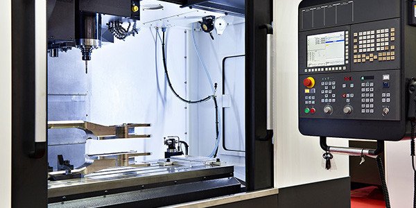
Solving the challenges of large-part machining first requires a machine tool capable of “dominating” the task. Traditional high-speed light-duty machining centers are unsuitable for heavy-duty cutting. Consequently, specialized heavy-duty gantry machining centers and floor-type boring and milling machines have become the mainstay.
1. High-Rigidity Machine Beds and Structural Optimization
The design philosophy of modern heavy-duty machine tools is to “absorb vibration” rather than just “resist it forcefully.”
-
Polymer Concrete Fill: Many high-end machine tools use composite structures for major components like beds and columns, combining cast iron frameworks with mineral casting (polymer concrete). This material possesses excellent damping properties, with vibration absorption capacity 6-10 times greater than ordinary cast iron. It acts like a sponge, absorbing vibrational energy generated during cutting and preventing vibration waves from transmitting to the machining area.
-
Topology Optimization via Finite Element Analysis (FEA): Using FEM technology for topology optimization of the machine structure allows for placing reinforcement ribs in key load-bearing paths while removing material from non-stressed areas. This achieves an ideal state of “rigidity where needed, lightness where possible.”
2. Large Cross-Section Rams and Balancing Systems
For the ram components required to machine deep cavities, modern machine tools employ large cross-section, rectangular, or octagonal slideway designs, significantly enhancing torsional rigidity. Simultaneously, they are equipped with hydraulic or nitrogen balancing systems that constantly offset the weight of the ram and spindle head. This prevents vertical droop caused by gravity, ensuring accurate geometric positioning at any point along the Z-axis travel.
Chapter 3: The Wisdom of Process and Programming: Outsmarting, Not Overpowering
With a powerful hardware platform, intelligent process software is needed to achieve maximum effect with minimal force—the principle of “four ounces moving a thousand pounds.”
1. Dynamic Machining and Trochoidal Milling
Traditional roughing pursues large depths and widths of cut, but this generates enormous cutting forces, easily inducing vibration. Dynamic Milling techniques promoted by modern CAM software achieve effective control of cutting forces through strategies involving “light axial depth, high feed rate, and large arc engagement.”
-
Trochoidal Milling: The tool follows a circular toolpath, controlling the radial engagement angle to keep cutting forces constant. This “soft overcomes hard” approach significantly reduces radial impact, protects thin-wall structures, and allows for higher spindle speeds and feed rates.
2. Non-Constant Lead and Variable Pitch Tools
Tool manufacturers have developed specific vibration-damping tools to address chatter.
-
Variable Pitch End Mills: Traditional milling cutters have evenly spaced flutes, which can easily generate vibrations at a fixed frequency. Variable pitch tools disrupt the periodicity of the vibration, preventing harmonics from superimposing and thus effectively blocking resonance.
-
Vibration-Damping Tool Holders: For deep cavity machining, heavy-duty tool holders with built-in “dynamic vibration absorbers” are used. These holders contain precisely tuned mass elements and damping components. When the holder vibrates during bending, the internal mass moves in the opposite direction, instantly dissipating vibrational energy.
3. Intelligent Adaptive Machining
Integrating sensors and closed-loop control enables true intelligence.
-
In-Process Measurement and Compensation: After roughing, the machine tool’s probe performs in-process inspection to obtain actual deformation data. The system automatically adjusts the finishing toolpaths based on this data to perform error compensation, ensuring the final contour meets drawing requirements.
-
Cutting Force Monitoring: Force sensors integrated into the spindle or worktable constantly monitor the cutting load. If abnormal impacts or vibrations are detected, the control system automatically fine-tunes the spindle speed or feed rate, keeping the process within the stable cutting region.
Chapter 4: The Art of Fixturing and Support: Dividing to Conquer and Multi-Point Fixing
How do you secure a 10-ton, irregularly shaped workpiece? Traditional clamp-down methods often induce clamping deformation. When the clamps are released, the workpiece springs back, rendering machining accuracy meaningless.
1. Flexible Support Systems
Modern large-part machining increasingly utilizes adaptive support units. These hydraulically or pneumatically controlled support cylinders are distributed beneath the workpiece. During setup, the supports first rise rapidly to contact the workpiece’s underside, then apply a minimal locking force. Rather than forcefully pressing the workpiece down like clamps, they “cradle” it, counteracting gravity and cutting forces. During finishing, support forces can even be adjusted in real-time to counteract warping caused by stress relief.
2. Vacuum Chucks and Magnetic Tables
For large plates or frame-like parts, vacuum chuck platforms provide uniform clamping force, avoiding localized deformation caused by point clamping. For ferromagnetic materials, permanent or electromagnetic tables can quickly and extensively hold the workpiece, with magnetic force penetrating the surface, allowing for five-sided machining in a single setup.
3. Stress Pre-Release Techniques
During the roughing stage, leave a sufficient allowance (e.g., 3-5mm), then remove the workpiece from the machine and let it sit for a period (natural aging) or subject it to vibratory stress relief. Allow the internal stresses to release and the workpiece to fully deform, then perform a second setup for finishing. This “roughing and finishing separation” technique, while time-consuming, is a classic method for ensuring ultra-high precision in large parts.
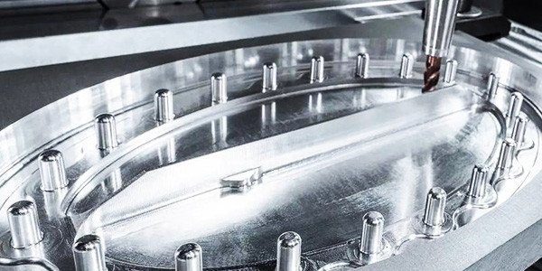
Chapter 5: Practical Case Study: Machining a Large Wind Turbine Gearbox Housing
Consider the core component of wind power equipment—the gearbox housing. This part typically measures around 3m x 2m x 1.5m, with wall thicknesses of only 20-30mm, and features complex thin-wall rib structures and multiple precision bearing bores internally. Machining challenges include:
-
Bearing Bore Concentricity: The multiple bearing bores span a large distance, requiring concentricity within 0.03mm.
-
Thin-Wall Deformation: When machining the sides and top, the housing walls are highly prone to chatter.
Combined Solution:
-
Equipment: A high-rigidity five-face gantry machining center equipped with extended, vibration-damping boring bars.
-
Fixturing: Use of multiple hydraulic support units with 8 support points placed under the housing base and floating supports on the sides to eliminate clamping stress.
-
Process:
-
Perform rough machining first to remove the bulk of the allowance.
-
Apply vibratory stress relief.
-
Semi-finish all surfaces, leaving a 0.5mm allowance.
-
Finish bore machining: Use boring bar steady rests to assist in supporting the long boring bar and apply minimum quantity lubrication to reduce cutting heat.
-
Final surface finishing: Use a large-diameter face mill cutter head with variable-pitch inserts, employing climb milling and low radial engagement parameters.
-
-
Result: Through this comprehensive approach, vibration was successfully suppressed within allowable limits, the concentricity of the multiple bearing bores was ensured, machined surfaces were free of chatter marks, and the yield rate increased to over 98%.
Chapter 6: Future Trends: Digital Twins and Intelligent Control
Looking ahead, solutions to the vibration and deformation challenges in large-part machining will become even more digitalized.
-
Digital Twin Simulation: Creating a “digital twin” in a virtual environment that incorporates the machine tool’s dynamic characteristics, the workpiece blank’s stress field, and cutting parameters. Before actual machining, potential deformation and vibration throughout the process can be predicted through simulation, allowing for automatic optimization of toolpaths and cutting parameters.
-
Active Vibration Control: Developing intelligent spindles or worktables integrating piezoelectric actuators. Sensors monitor vibration in real-time, the control system instantly calculates a reverse waveform and drives the actuators to generate a counteracting force, achieving “active cancellation” of vibration.
Conclusion
The challenges of vibration and deformation in CNC machining of large parts represent a pinnacle problem in manufacturing. There is no single “silver bullet”; it requires a systematic engineering effort integrating multidisciplinary knowledge. Through high-damping machine tool hardware, intelligent CAM strategies, innovative vibration-damping tools, and scientific fixturing techniques, modern manufacturing technology has transformed what were once considered “unmachinable” large thin-walled parts into precision components meeting the highest accuracy standards.
With the continuous emergence of new materials and processes, we have reason to believe that the future of large-part machining will be even more assured, allowing the manufacturing philosophy of “a heavy sword has no edge, great skill appears effortless” to be perfectly realized amidst the roar of the workshop floor.
Choose Gazfull CNC Machining Services
At Gazfull, we specialize in providing machining services that go beyond traditional manufacturing. We aim to optimize your processes and reduce production expenses while delivering high-quality results. Our expertise and state-of-the-art 3-axis cutting systems also enable us to handle all your custom needs efficiently and precisely.
Recent Posts
Gazfull CNC Machining Services

Custom CNC Metal Parts Machining Service
Gazfull CNC Machining, A manufacturer for CNC Machining Metal Parts. We offer metal fabrication service and custom manufactured parts factory service.
CNC Machining for Low Volume Production
We offer a full suite of CNC capabilities — including 3, 4, and 5-axis milling, Swiss-style turning, conventional turning, and mill-turn machining — to support low volume production.
CNC Machining for High Volume Machining
High-volume CNC machining utilizes advanced computer-controlled machines that can execute machining operations at significantly higher speeds than traditional manual methods.
CNC Cutting Service
We are able to provide 2D and 3D product designs in a variety of colors. We excel at laser cutting hard and delicate materials, difficult and complex projects, and both large and small projects.
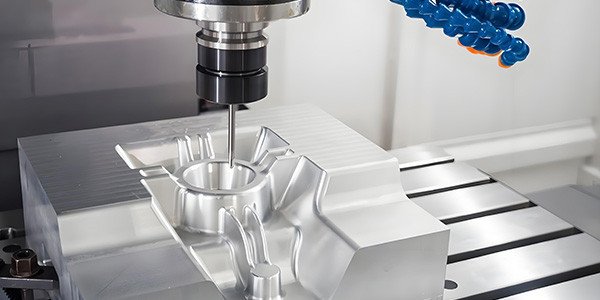
CNC Milling Service
We have dozens of in-house 5-axis CNC milling machines that can easily mill plastic and metal parts with tight tolerances and complex geometries. We also use 3-axis and 4-axis milling machines to provide low-cost machined parts.
CNC Turning Service
Our commitment to excellence and dedication to transparency and efficiency have made us a key player in promoting the production and delivery of CNC turning parts, further improving the quality and precision of parts in various industries.
CNC Routing Service
CNC routing offers several advantages over traditional manual routing or other manufacturing methods. For example, plasma or laser cutting.

CNC Product Surface Treatment
CNC product surface treatment involves post-machining processes like anodizing, powder coating, electroplating, and polishing to enhance appearance, corrosion resistance, wear.

CNC Machining Metal Fabrication Service
Providing high-quality CNC Machining Fabricating Services services in China for a wide range of mechanical products, assemblies, and custom parts.
CNC Prototype Machining Service
CNC Rapid prototyping services are essential to modern advanced manufacturing, enabling engineers and product developers to move from concept to functional parts in days rather than months.
CNC Machining Low Volume Manufacturing
Low volume manufacturing (LVM) is characterized by production runs that are too small for high-volume techniques but too large for one-off prototyping.
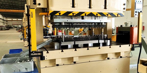
Custom Metal Stamping Service
Metal stamping is a cold-forming fabrication method that’s simple yet versatile. In this process, flat metal strips are fed into stamping equipment with tooling or dies.
Custom Die Casting Service
Gazfull partners with the leading extrusion suppliers who utilize the most sophisticated technology to deliver high-quality extrusions.
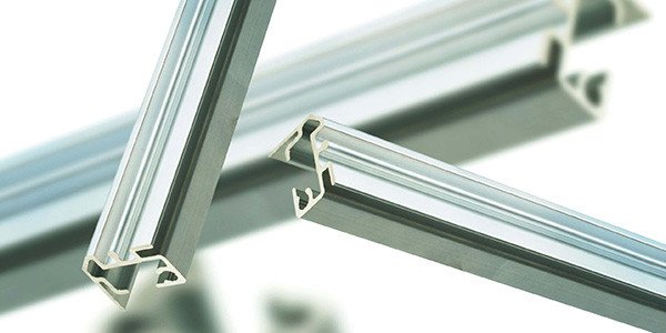
Metal Extrusion Service
Metal extrusion is the manufacturing process of choice when producing high volumes of material with a constant cross-section. With the extrusion process, metal material is forced through the shaped opening of a die using high pressure, resulting in an extruded profile.
Get a quote
Email:info@gazfull.com
Ready to get started on your next project?
From one part to thousands of parts, we can help you accelerate your sheet metal projects using CNC machining Services in a cost-effective way. Contact us right now! info@gazfull.com