Small Metal Lathe Parts Manufacturing Process
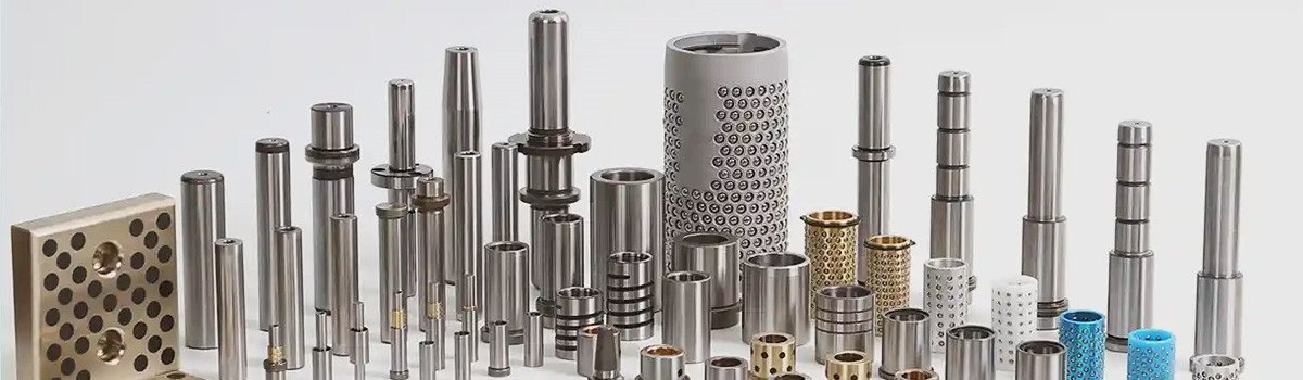
Manufacturing small metal lathe parts involves CNC turning (lathe machining) for cylindrical shapes, where a rotating workpiece is cut by a stationary tool, often with live tooling for complex features like threads and grooves, or Metal Injection Molding (MIM) for intricate, mass-produced components, combining metal powder with binders, followed by debinding and sintering for density. The process starts with raw material (bar stock or powder), uses programmed machines (CNC lathes) for precision, and may include finishing steps like bead blasting or plating for surface quality.
Table of Contents
ToggleKey Processes for Lathe Parts
1. CNC Turning (Machining): The Core Process for Lathe Parts
- Facing: Creating a flat end surface.
- Roughing and finishing: Removing bulk material then achieving smooth surfaces and tight tolerances (often ±0.0005 inches or better).
- Turning diameters: Producing straight or contoured cylindrical sections.
- Threading: Cutting external or internal threads.
- Grooving: Forming O-ring grooves, snap-ring channels, or parting-off features.
2. Metal Injection Molding (MIM): An Alternative for Complex, High-Volume Small Parts
3. Other Processes for Complex Features on Lathe Parts
- Milling: Performed on CNC mills or via live tooling on lathes, milling creates flats, pockets, slots, keyways, or contoured surfaces on otherwise cylindrical parts. It uses rotating multi-point cutters on a stationary (or indexed) workpiece, complementing turning for hybrid geometries.
- Broaching: This involves a toothed tool pulled or pushed through the workpiece to cut precise internal or external shapes like keyways, splines, or serrations in a single pass (or sequential shallow cuts). Rotary broaching (wobble broaching) can be done on CNC lathes using specialized attachments, enabling efficient formation of polygonal holes or profiles without secondary setups.
- Drawing/Extruding: These are upstream processes for preparing raw stock. Wire or rod drawing pulls metal through dies to achieve uniform cross-sections (e.g., round bars with specific diameters), while extrusion forces material through shaped dies for consistent profiles. These ensure high-quality starting material for subsequent turning operations.
Common Operations in Small Metal Lathe Parts Manufacturing
Key Processes for Lathe Parts:
*Turning: The primary subtractive process reduces the diameter of the workpiece to create straight cylinders, tapers, shoulders, or contours. Rough turning removes bulk material quickly, while finish turning achieves precise dimensions and excellent surface finishes (often Ra 0.8 μm or smoother). For small parts, this operation ensures concentricity and roundness critical for shafts, pins, and bushings.boyiprototyping.com
*Facing: This creates a flat, perpendicular end surface by feeding the tool radially across the rotating end of the part. It establishes a clean reference face for subsequent operations or ensures proper length and squareness.
*Drilling and Boring: Drilling produces axial holes using rotating drills held in the turret or tailstock. Boring enlarges or refines these holes for precision fit, often using single-point boring bars to achieve tight tolerances and smooth bores in small bushings or fittings. Live tooling on advanced lathes allows cross-drilling for radial features without repositioning.
*Threading: External threads are cut using single-point threading tools that follow a helical path synchronized with spindle rotation. Internal threads use taps or boring tools. CNC control enables precise pitch, lead, and multi-start threads on small fasteners, connectors, or adjustment screws.partmfg.com
*Knurling: A forming (not cutting) operation presses a knurling tool against the rotating workpiece to create a diamond, straight, or diagonal textured pattern. This improves grip on knobs, thumbscrews, handles, or adjustment collars without adding significant diameter.reidsupply.com
Swiss-type CNC lathes are particularly suited for very small parts (down to sub-millimeter features) due to the guide bushing that supports the stock close to the cutting zone, reducing deflection and enabling high-aspect-ratio components like medical screws or watch pins.
Post-Processing Steps
After primary machining, small parts undergo finishing to remove imperfections and enhance performance:
1.Deburring and Finishing: Sharp edges, burrs from turning or drilling, and tool marks are removed through manual deburring, vibratory tumbling, or media blasting. Bead blasting (using glass or ceramic beads) or tumbling with abrasive media smooths surfaces, improves aesthetics, and prepares parts for coatings. These steps prevent stress concentrations and ensure safe handling.comcoinc.com
2.Surface Treatments: To boost corrosion resistance, wear properties, or appearance, common treatments include:Electroplating (nickel, chrome, zinc) for decorative or protective layers.
*Anodizing (for aluminum) to create a hard, insulating oxide film.
*Passivation (for stainless steel) to enhance corrosion resistance.
*Painting, powder coating, or PVD/CVD coatings for specialized needs.
These treatments extend service life in demanding environments like medical, aerospace, or marine applications.
Ideal Use Cases for Key Processes
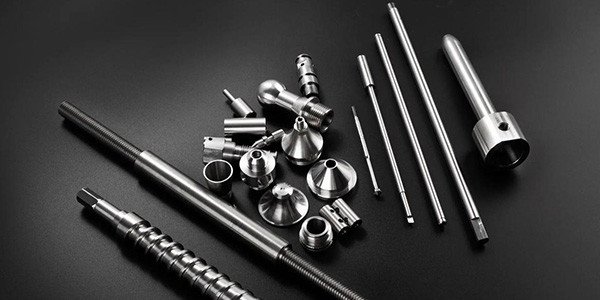
1.CNC Lathes (including Swiss-type): Best for precision small parts requiring excellent concentricity, surface finish, and moderate to high complexity in rotational features. Typical applications include:
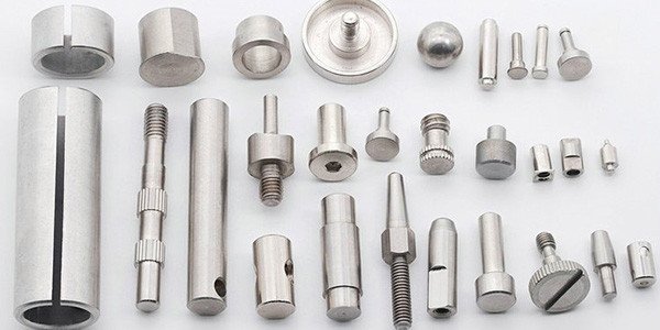
*Shafts, rods, and spindles.
*Bushings, spacers, and bearings.
*Threaded fasteners, connectors, and fittings.
*Automotive sensor housings, aerospace fittings, and medical instrument components.
*CNC turning offers flexibility for prototypes to medium runs (hundreds to thousands), with quick setup changes and material efficiency.
2.Metal Injection Molding (MIM): Ideal for very small, highly complex parts produced in large volumes (tens of thousands to millions). MIM starts with metal powder mixed with a binder, injected into molds, debound, and sintered to near-full density. It excels at features like thin walls, undercuts, internal cavities, fine textures, or integrated multiple elements that would be costly or impossible to machine efficiently.unionfab.com
Common MIM applications for small metal parts include medical device components (e.g., surgical tools, orthodontic brackets), micro-gears, intricate brackets, firearm triggers, and electronic connectors. While tooling costs are higher upfront, MIM reduces waste, secondary operations, and assembly steps for cost-effective mass production.
In practice, manufacturers often hybridize approaches: a part might be MIM-formed for complex geometry then finish-machined on a CNC lathe for critical tolerances, or turned parts may receive MIM-like secondary features if volume justifies it.
Overall, producing small metal lathe parts combines subtractive precision (via CNC turning) with near-net-shape efficiency (via MIM) and essential post-processing to meet stringent requirements for size, accuracy, durability, and functionality in modern miniaturized applications.
Materials Selection for Small Metal Lathe Parts
Choosing the right material is pivotal in the manufacturing process, as it influences machinability, durability, and cost. Common metals for small lathe parts include aluminum, brass, steel, stainless steel, copper, and titanium. Each has unique properties: aluminum is lightweight and easy to machine but soft; brass offers excellent corrosion resistance and is ideal for decorative or electrical parts; steel provides strength but can be challenging for tiny features due to hardness.
Design and Planning
Effective design and planning mitigate risks in manufacturing small metal lathe parts. Start with CAD software like SolidWorks or Fusion 360 to model the part, incorporating tolerances, surface finishes, and features like threads or grooves. For small parts, designs must account for tool access—avoid deep undercuts that could cause tool breakage.
Planning includes process sequencing: rough turn to remove bulk material, then finish passes for precision. Simulate operations using CAM software to generate G-code for CNC lathes, optimizing feeds and speeds. For manual lathes, create detailed drawings with dimensions.
Consider fixturing: collets for precise holding of small diameters, or custom bushings to support delicate parts. Batch planning for high volumes involves bar feeders on automatic lathes. Risk assessment covers potential issues like chatter (vibration causing poor finish) or burr formation. Plan coolant use to dissipate heat, especially in stainless steel. Time estimates help in scheduling: a simple small shaft might take 5-10 minutes per part manually, less on CNC.
Prototyping validates the plan—machine a test part, measure with micrometers or CMM, and iterate. Documentation ensures repeatability.
Lathe Setup and Tools
Setup is where precision begins. For a mini lathe, secure it on a stable bench, level the bed, and align the headstock and tailstock. Parts of the lathe include the bed, headstock (with spindle), carriage, and tailstock.
Mount the workpiece in a 3-jaw chuck for general use or collet for high precision on small diameters. Use a center drill if tailstock support is needed.
Tools: High-speed steel (HSS) for soft metals like brass, carbide inserts for harder ones. Grind tools to specific angles—e.g., 60° for threading. Tool height must align with the spindle centerline.
Speeds and feeds: Calculate RPM as (Cutting Speed x 4) / Diameter. For brass, 1000-2000 RPM on small parts; feeds 0.002-0.005 inches per revolution. Use cutting fluids for lubrication.
For micro parts, employ steady rests or follow rests to prevent flexing. Calibration with dial indicators ensures accuracy.
Machining Operations
The core of the process involves several operations, each tailored for small parts.
Facing: Square the workpiece end by advancing the tool perpendicularly. For small parts, light cuts (0.005 inches) prevent tool dig-in.
Turning: Reduce diameter by moving the tool parallel to the axis. Roughing removes most material, finishing achieves final dimensions. On tiny parts, use high RPM to maintain surface speed.
Drilling and Boring: Center drill first, then drill holes. Boring enlarges them precisely. For small bores, use carbide drills to avoid wander.
Threading: Cut threads with a die or single-point tool. On small parts, external threads are common; ensure rigid setup.
Parting: Cut off the finished part with a thin blade tool. Support with tailstock if possible.
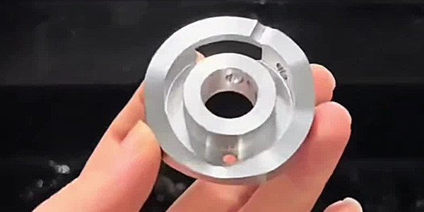
Knurling and Grooving: Add texture or slots. For micro features, specialized tools are needed.In CNC, live tooling allows off-axis milling. Examples: Machining a 0-80 brass flange nut involves drilling, tapping, and turning in sequence.
For very small parts, like 0.5mm chamfers, custom jigs or secondary operations (e.g., sanding) may follow. Heat management is crucial—excess can warp thin sections.
Deburring removes sharp edges, often manually with files or tumblers.
Safety and Quality Control
Safety is paramount: Wear PPE, secure loose clothing, and use guards. Avoid reaching into spinning parts; stop the machine for adjustments.
Quality control uses micrometers, calipers, and optical comparators for dimensions. Surface roughness testers check finishes. For small parts, magnification aids inspection.
Implement SPC to monitor variations. Common defects: out-of-roundness from poor chucking, burrs from dull tools.
Advanced Techniques
CNC integration automates processes, with Swiss lathes excelling for complex small parts. Hybrid methods combine lathe with 3D printing for prototypes.Multi-axis turning adds features like slots without repositioning.
Conclusion
The manufacturing process for small metal lathe parts blends art and science, delivering precision components vital to innovation. Mastery comes with practice, adapting to evolving technologies for efficiency and quality.