CNC Machining Process
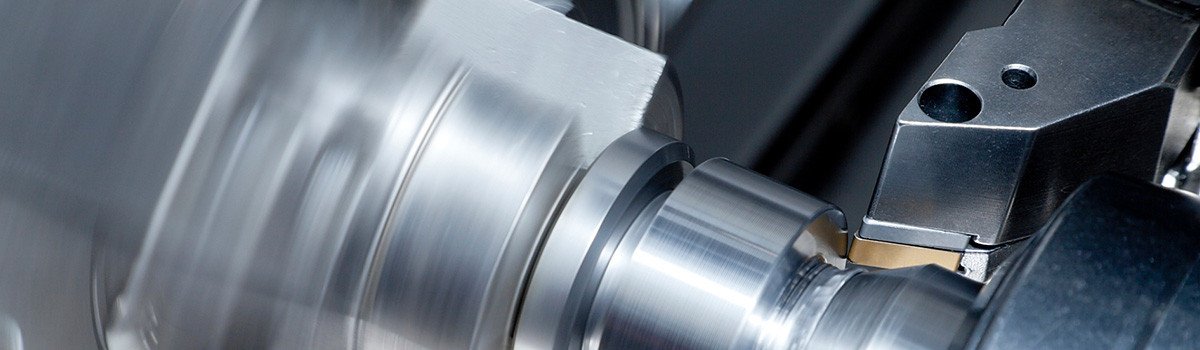
Table of Contents
ToggleHistory of CNC Machining
How CNC Machining Works
- Machine Frame and Bed: Provides stability; cast iron or polymer concrete bases minimize vibrations.
- Spindle: Rotates the cutting tool at speeds up to 100,000 RPM in high-speed applications.
- Axes: Most machines have 3 axes (X, Y, Z), but advanced ones feature 4, 5, or more for complex orientations.
- Tool Changer: Automatically swaps tools, reducing downtime.
- Coolant System: Manages heat and chip removal, using flood coolant or mist.
The CNC Machining Process: Step by Step
Step 1: Design – Creating the Digital Blueprint
The CNC machining process begins with design, where engineers create a detailed Computer-Aided Design (CAD) file. Using software like SolidWorks, AutoCAD, or Fusion 360, designers specify the part’s exact geometry, dimensions, features, and tolerances. This 3D or 2D model serves as the foundation for everything that follows.
A well-crafted CAD file is crucial because it must account for manufacturability—considering factors like material properties, tool access, and potential stresses. For complex parts, designers incorporate features such as fillets to reduce sharp corners or draft angles for easier machining. The file is typically exported in formats like STEP or IGES for compatibility with downstream software.This step allows for virtual testing and iterations, reducing errors before any material is cut. Modern CAD tools even simulate real-world performance, ensuring the design meets functional requirements.
Step 2: Programming – Translating Design into Machine Instructions
Once the CAD model is complete, skilled technicians use Computer-Aided Manufacturing (CAM) software to generate the machining program. Tools like Mastercam or Autodesk PowerMill interpret the CAD geometry and create toolpaths—the precise routes cutting tools will follow.
The CAM software outputs G-code (for movements, speeds, and coordinates) and M-code (for auxiliary functions like coolant activation or tool changes). It selects optimal tools, calculates feed rates, spindle speeds, and strategies for roughing (bulk material removal) versus finishing (surface refinement).Simulation features in CAM allow programmers to visualize the process, detecting potential collisions or inefficiencies. This step bridges the digital design and physical production, ensuring the machine executes operations safely and efficiently.
Step 3: Setup – Preparing the Machine and Workpiece
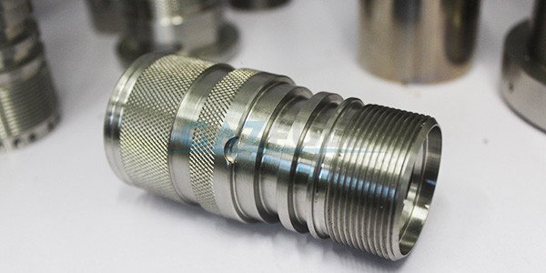
With the program ready, the setup phase begins. The raw material—a block, bar, or sheet of metal (e.g., aluminum, steel) or plastic—is securely clamped into the CNC machine using vises, fixtures, or chucks to prevent movement during cutting.
Tools are loaded into the machine’s tool changer or spindle, selected based on the part’s requirements (e.g., end mills for slots, drills for holes). The operator sets work offsets—establishing the zero reference point aligning the CAD coordinates with the physical workpiece. Probes or edge finders ensure precise positioning.
Coolant systems are primed, and a dry run (simulated operation without cutting) verifies the program. Proper setup is vital for accuracy and safety, minimizing risks like tool breakage.
Step 4: Machining – Executing the Automated Process
The core of CNC machining occurs here: the machine follows the programmed instructions to remove material precisely. Cutting tools rotate at high speeds while moving along multiple axes (typically 3-5, or more for advanced machines), milling, turning, drilling, or grinding the workpiece.
Common operations include milling (rotating cutters remove material from a stationary piece) and turning (rotating the workpiece against a stationary tool). Multi-axis machines enable complex undercuts and contours in one setup.
The process is highly automated, running unattended for hours with sensors monitoring for issues. Coolant flushes chips and controls heat, extending tool life.
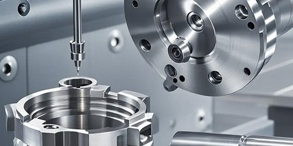
Step 5: Quality Control – Ensuring Precision and Standards
After machining, the finished part undergoes rigorous quality control. Measurements using calipers, micrometers, CMMs (Coordinate Measuring Machines), or optical scanners verify dimensions against tolerances.
Surface finish, hardness, and material integrity are inspected. Non-destructive testing may check for internal defects. Any deviations trigger adjustments to the program or setup for future runs.
This step ensures reliability, especially in critical applications like aerospace or medical devices.
Types of CNC Machines
CNC Mills
CNC Lathes
CNC Routers
CNC Plasma Cutters
CNC Laser Cutters
CNC EDM (Electrical Discharge Machining)
CNC Grinders
Materials Used in CNC Machining
Metals
- Aluminum: Lightweight, corrosion-resistant, excellent machinability. Alloys like 6061 for structural parts, 7075 for aerospace.
- Steel: Versatile; mild steel for general use, stainless for corrosion resistance. Tool steels like D2 for dies.
- Titanium: High strength-to-weight ratio, biocompatible. Challenging due to low thermal conductivity; requires sharp tools and coolants.
- Brass and Copper: Soft, conductive; used in electronics and plumbing.
Plastics
- ABS: Tough, impact-resistant; common in consumer products.
- Nylon: Wear-resistant, low friction; for gears and bearings.
- Polycarbonate: Transparent, strong; optical applications.
- PEEK: High-temperature resistant; medical and aerospace.
Composites
- Carbon Fiber Reinforced Polymers (CFRP): Lightweight, strong; aerospace and automotive. Requires diamond-coated tools to avoid delamination.
- Fiberglass: Cost-effective alternative.
Exotic Materials
- Inconel and Hastelloy: Superalloys for extreme environments; slow machining speeds.
- Ceramics: Hard, brittle; used in electronics. Advanced techniques like ultrasonic machining aid processing.
Advantages and Disadvantages of CNC Machining
Advantages
- Precision and Accuracy: Tolerances as tight as ±0.001 inches, repeatable across batches.
- Efficiency: Reduced labor costs; machines run 24/7 with minimal supervision.
- Flexibility: Quick program changes for design iterations.
- Complex Geometries: Multi-axis capabilities for intricate parts.
- Waste Reduction: Optimized toolpaths minimize scrap.
- Scalability: From prototypes to mass production.
Disadvantages
- High Initial Costs: Machines and software are expensive; setup for small runs uneconomical.
- Skill Requirements: Programming demands expertise; errors lead to crashes.
- Material Limitations: Not ideal for very large parts or certain soft materials.
- Maintenance: Regular calibration and tool replacement needed.
- Environmental Impact: Energy consumption and coolant disposal issues.
Applications of CNC Machining
Aerospace
Automotive
Medical
Electronics
Defense
Energy
Future Trends in CNC Machining
- AI Integration: Predictive maintenance, adaptive machining.
- Additive-Subtractive Hybrids: Combine 3D printing with CNC finishing.
- Sustainability: Eco-friendly coolants, energy-efficient machines.
- IoT and Digital Twins: Real-time monitoring, virtual simulations.
- Nanomachining: Sub-micron precision for microelectronics.
- Automation: Robotic loading/unloading for lights-out manufacturing.